
Antennas are structures designed for radiating electromagnetic energy effectively in a prescribed manner.Without an efficient antenna, electromagnetic energy would be localized, and wireless transmission of information over long distances would be impossible.
An antenna may be a single straight wire or a conducting loop excited by a voltage source, an aperture at the end of a wavelength, or a complex array of these properly arranged radiating elements.
Some different types of antennas are given below:
1. MONOPOLE

2.DIPOLE(Full Wave)

3. FOLDED DIPOLE

4. HELICAL

5. YAGI

6. DIPOLE(Half Wave)
Polarization:
The polarization describes the time varying behavior of the electric field intensity vector at a given point in space.
Now let us see polar diagrams of different antennas.
Procedure:
Assembled the exercise equipment as in the Fundamentals of Antenna Technology, according to the instructions on the introduction pages.
Procedure is same for all experiments:
The X-band LNC SO4100-8A and the micros trip antenna SO4100-8N form the test receiver. Connected both together using the N-connector. insert the test receiver in the holder on the antenna stand, SO4100-8E. Turn the test receiver together with the micro strip antennae.
Aligned the stand with the test receiver to the transmitter platform. The height of the antennae was aligned to the centre. The distance between transmitter and receiver, for all exercises, was kept between 0.5 ... 0.8 m.
1. Draw the Polar Diagram of Horizontally Polarized.
2. Draw the Polar Diagram of Vertically Polarized.
3. Combined the above two polar diagrams.
.
Polar Diagram of Monopole:
Measured value on the level meter. - 60.2
Measured value on the frequency meter: 8.54 GHz
Horizontally Polarized Monopole:

Vertically Polarized Monopole:

3_Dimentionally Monopole:
Comments:
A monopole mounted vertically for vertical polarization does not exhibit any directivity in the horizontal plane.
In the vertical plane, a monopole exhibits maximum radiation in the direction of the radiating element.
In the direction of the ground plane, the monopole exhibits a series of small side lobes.
Polar Diagram of Dipoles:
Measured value on the level meter: -72 dBm
Measured value on the frequency meter. 8.54 GHz
Horizontally Polarized Dipoles.

Vertically Polarized Dipoles:

3_Dimentional Diagram Dipoles:

Comments:
A dipole that is mounted for horizontal polarization exhibits two radiation maxima in the horizontal plane.
These radiation maxima are perpendicular to the axis of the dipole group.
A minimum is formed along the length of the dipole.
In the vertical plane, the dipole does not exhibit any directivity
Polar Diagram of Folded Dipoles:
Measure the value on the level meter: -50.4 dBm
Measure the value on the frequency meter: 8.54 GHz
Horizontally Polarized Folded Dipoles.

Vertically Polarized Folded Dipoles:

3_Dimentional Diagram Folded Dipoles:

Comments:
A folded dipole that is mounted for horizontal polarization exhibits two radiation maxima in the horizontal plane.
These radiation maxima are perpendicular to the axis of the folded dipole.
A minimum is formed along the length of the folded dipole.
In the vertical plane, the folded dipole does not exhibit any directivity.
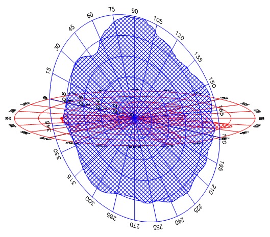
Polar Diagram of Yagi Antennae:
Measured value on the level meter: -28 dBm
Measured value on the frequency meter: 8.54GHz
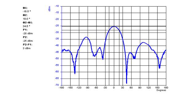
Horizontally Polarized Yagi Antennae.

First, set marker P1 for the received level to a maximum in the 0° direction.
Now, set marker P2 to the point where the level is 3dBm lower.
At the left of the display, the detail P2-P1=-3dBm is shown.
Now determine the apex angle of the Yagi antenna. Use the angle markers Φ1 and Φ2.
Measure the apex angle Φ2 - Φ1 °

Vertically Polarized Yagi Antennae:

3_Dimentional Diagram Yagi Antennae:

Comments:
If a folded dipole is fitted with a reflector and additional so-called directors, then a the directional properties are improved in the direction of the main beam.
Antennae that use this form of construction, are called Yagi-antennae.
The apex angle of a 3-element Yagi-antenna is approximately 40° a thus, considerably narrower than that of a simple folded dipole.
Polar Diagram of Helix Antennae:
Measured value on the level meter: dBm
Measured value on the frequency meter: GHz
Horizontally Polarized Helix Antennae:

Evaluation of Cartesian polar diagram for the horizontal plane.
(Measurement of Apex Angle):
First, set marker P1 for the received level to the maximum in the 0° direction.
Now, set marker P2 to the point where the level is 3dBm lower. At the left of the display, the detail P2-P1=-3dBm is shown.
Now determine the apex angle of the helix antenna. Use the angle markers Φ1 and Φ2.
Measure the apex angle Φ2 - Φ1: °
Vertically Polarized Helix Antennae:

3_Dimentional Diagram Helix Antennae:

Comments:
In the horizontal plane, a helix antenna exhibits a clear radiation maximum.
In the vertical plane, a helix antenna exhibits a similar directivity as in the horizontal plane since it is circular polarized
The apex angle of a helix antenna is approximately 30°.


No comments:
Post a Comment